
PNP and NPN transistor – differences, applications
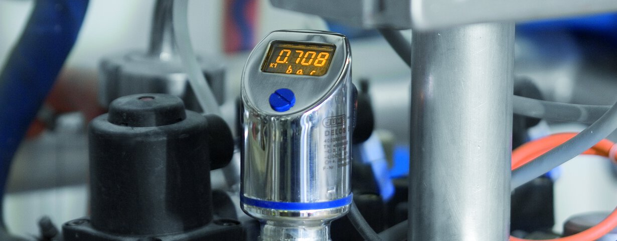
Thanks to transistors, which were developed in the 20th century, electronics has developed at a rapid pace. Today, they are the basic building block of a very large number of electronic circuits, such as current sources, generators, stabilisers and, above all, microprocessors, among others. Bipolar transistors - NPN and PNP - are one type of transistor. From the following post, you will learn how they work, how they differ from each other and how to wire them. You will also learn about the practical aspects of using NPN and PNP transistors in the JUMO DELOS SI pressure transmitter.
Table of Content
What is a transistor?
A transistor is a 3- or 4-electrode, semiconductor electronic element that has the ability to amplify, control, generate or switch electrical signals. These devices are most commonly used as components of microprocessors.
Transistor as a switch
Bipolar transistors are used in various amplifying and modulating circuits. The most common application is full on/off operation, referred to as a switch. They can also be used as amplifiers or oscillators.
Bipolar junction transistor, or PNP transistors and NPN transistors
NPN and PNP transistors are bipolar junction transistors. Two types of carriers are involved in the conduction of current in these transistors: electrons and holes. Bipolar transistors are formed by combining three layers of P and N semiconductors and come in two basic varieties: NPN (Negative-Positive-Negative) and PNP (Positive-Negative-Positive).
Regardless of which variety we are dealing with, there are always three leads in these transistors, as: E (emitter), B (base) and C (collector). The small current that flows between the base and emitter is used to control the larger current that flows between the collector and emitter.
NPN transistor
The NPN transistor is the most commonly used bipolar transistor. It is constructed by placing a P-type semiconductor between two N-type semiconductors. In this type of transistor, the current flows in the collector-emitter direction. The NPN transistor turns on when current flows through the base of the transistor.
PNP transistor
A PNP transistor 'turns on', i.e. opens the channel between emitter and collector, when a small current flows from the emitter to the base of the transistor. For a base current to flow in a PNP transistor, the base must be more negative than the emitter by about 0.7V for silicon components and about 0.3V for germanium components.
The structure of a PNP transistor is completely opposite to that of an NPN transistor. A PNP transistor consists of an N-type semiconductor between two P-type semiconductors. Transistors of this type can also be used as electronic switching elements.
PNP transistors vs NPN transistors - the difference
The PNP and NPN transistor differ in voltage polarity and direction of current flow. In an NPN, the current flows in the direction from the collector terminal to the emitter terminal, whereas in a PNP transistor the current travels in the opposite direction. Another difference between the two types of transistor is that holes are the more important carriers in the PNP transistor, while in the NPN they are electrons.
Main differences between an NPN transistor and a PNP transistor
-
voltage polarity (negative voltage and positive voltage)
-
current directions
PNP and NPN relay output - connection
The load must be connected to the PNP and NPN transistors in a specific way, as these bipolar transistors differ in the arrangement of the PN transitions.
PNP switching output
The load is connected to a switching output with GND acting as a reference point. When a certain pressure value is reached and the signal changes, the supply voltage (U+) 'turns off', allowing current to flow from U+ through the transistor and load to GND.
NPN switching output
The reference pin to which the load is connected is the switching output U+. When the signal changes due to the pressure value being reached, the supply voltage (U+) is 'switched on', allowing current to flow from U+ through the transistor and the load to GND.
PNP-transistor identification
To determine whether you are dealing with an NPN or PNP transistor, you must immediately measure the resistance between the leads: emitter, base and collector. Each pair of cables should be measured in both directions with a multimeter. The following results will be obtained:
- Emitter-base terminals: as in a normal diode, emitter and base current should flow in one direction.
-
Collector-base terminals: as in a normal diode, the collector-base current should flow in one direction.
-
Emitter-collector terminals: current should not flow in either direction.
PNP outputs of the JUMO DELOS SI pressure sensor
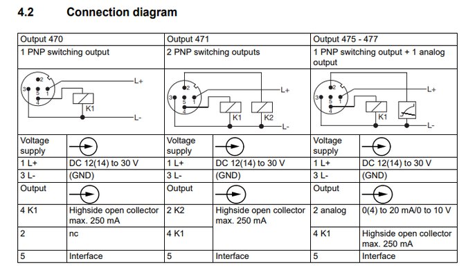
Depending on your requirement, the following output variants are available in the JUMO DELOS SI pressure transmitter: 1× PNP or 2× PNP switching outputs or 1× PNP switching output and analogue output signal.
JUMO DELOS SI pressure transmitter - available versions:
-
1 PNP switching output
-
2 PNP switching outputs
-
1 PNP switching output + 1 analogue output 4 to 20 mA1
-
1 PNP switching output + 1 analogue output 0 to 20 mA1
-
1 PNP switching output + 1 analogue output 0 to 10 V1

Connection diagram for JUMO DELOS SI pressure transmitter
Use of the PNP inputs of the JUMO DELOS SI pressure transmitter
Exceeding the set pressure
Thanks to the integrated PNP transistor, the JUMO DELOS SI pressure sensor takes action, such as triggering an alarm or switching off the pump, when the set pressure is exceeded.
Application of the JUMO DELOS SI pressure transmitter
-
Food and pharma
-
CIP/SIP systems
-
Machine and system construction
-
Construction of air-conditioning and refrigeration systems
Your benefits with the JUMO DELOS SI in a nutshell
-
Process safety
-
Hygienic design, with parts in contact with the medium made of stainless steel.
-
The system has no dead zones, which prevents microbiological contamination and ensures maximum process safety in hygienic processes.
-
Uncomplicated and time-saving
-
Time-saving thanks to easy local configuration of the measuring instrument or configuration via a more convenient configuration programme.
-
Flexibility
If you are interested in the JUMO DELOS SI or would like to learn more about our full range of pressure transmitters - please contact us!
About the Author
My name is Saskia van der Laan and I have been working at JUMO for quite some time, combining my professional skills with my passion for writing. Always with the aim of using written text to translate technology into practice and to inform and inspire the reader. In my spare time, I like to do sports and enjoy a long walk with the dog.


